FPI Installation, Commissioning & Technical Sketches
Plan the device locations, mounting details, radio links and acceptance tests together. These sketches explain the system arrangement and do not replace approved drawings or the manufacturer’s installation procedure.
1. Review the feeder before selecting locations
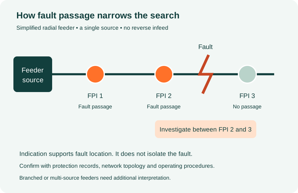
Start with the single-line diagram, feeder source, branches, normally open points, protective devices and possible reverse power flow. Identify where an indication would meaningfully separate fault-search sections. Record the phase arrangement, conductor diameter, available mounting locations and radio path to the proposed DCU. The catalogue configuration of nine FPIs per DCU is a capacity statement, not a universal placement rule.
2. Confirm the mounting method
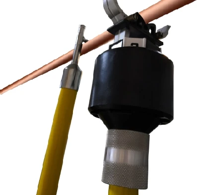
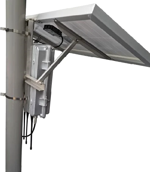
The source illustrates a conductor-mounted indicator handled with an MPE305 adapter and a telescopic insulating pole. It also shows the DCU and solar panel fixed to a pole by brackets and stainless straps. Installation on or near electrical conductors must be undertaken by authorised personnel using the utility-approved method, isolation or live-line procedure, suitable tools, clearances and protective equipment. The sketches below are explanatory, not live-line work instructions.
3. Register, configure and record
Before acceptance, associate every FPI and DCU ID with its feeder, phase and verified location. Agree fault-detection behaviour, reset modes, reporting intervals, communication parameters and authorised recipients. Keep the approved configuration and as-built location schedule as part of the project record. Confirm the manufacturer’s installation position and clamp condition without relying on an illustrative drawing.
4. Demonstrate local and remote operation
Use approved test equipment and procedures to demonstrate current measurement, the agreed fault response, visible indication and each reset method. Confirm the radio connection, cellular connection and backhaul recovery. Verify that faults, restoration and low-battery conditions appear at the intended monitoring destination with the correct device, phase, location and timestamp. Any SCADA commands should be tested only within the agreed acceptance procedure.
5. Handover and maintenance
Handover should include the final equipment list, approved settings, test records, drawings, user access, operating guide and warranty/support terms. Plan inspection of clamps, enclosures, pole straps, antenna connections and solar exposure according to manufacturer instructions. Review battery condition, event delivery and configuration records during maintenance; a catalogue service-life claim does not eliminate inspection or battery replacement.
Technical data and selection notes
Values below are transcribed or paraphrased from the supplied manufacturer catalogue. Entries marked for confirmation must be settled in the offered data sheet and approved project documents.
| Indicator envelope | W75 × H185 mm stated; not a complete fabrication drawing |
|---|---|
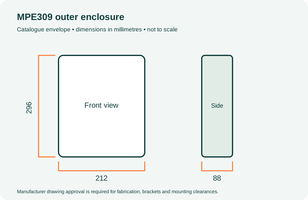
| DCU outer enclosure | 296 × 212 × 88 mm stated |
| DCU inner enclosure | 255 × 165 × 68 mm stated |
| Solar module | 670 × 350 × 25 mm, 30 W stated |
| Adapter interface | M33 × 2 illustrated |
| Conductor compatibility | 10–40 mm bare conductor stated; clamp and voltage class to be confirmed |
| Drawing status | Conceptual sketches only; no mounting clearances or structural design implied |
Fault-section sketch
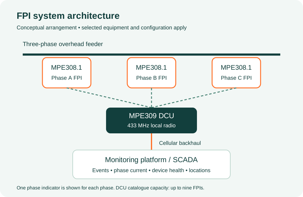
Communication architecture sketch
DCU enclosure dimension sketch
Mounting illustrations from the catalogue
Build the right FPI scope for your network
Share your feeder diagram and monitoring requirements. MPE can review equipment selection, supply, installation coordination and commissioning support as an agreed project scope.
Equipment selection, supply, installation coordination, testing and commissioning support for overhead fault indication and monitoring systems. Share your feeder diagram, voltage level, conductor details and SCADA requirements for a project-specific proposal.
Call / WhatsApp: +880 1558-607039 · Email: mechpowerengbd@gmail.com
Office: House-08 (GF), Road-06, Shekhertek Main Road, Dhaka 1207.
Factory: Ahasanpur, Bordeshi, Amin Bazar-1348, Savar, Dhaka, Bangladesh.
Final equipment ratings, test reports, integration scope, availability, software licensing and warranty terms are confirmed in the approved proposal.