MPE308.1 Overhead Fault Passage Indicator
A conductor-mounted fault indicator with a mechanical red flag, coloured LED indication and a 433 MHz local radio interface. It helps maintenance teams identify the section of an overhead feeder through which fault current has passed.
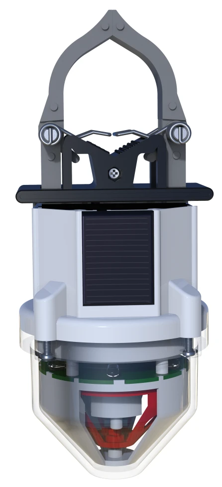
Fault location at the feeder
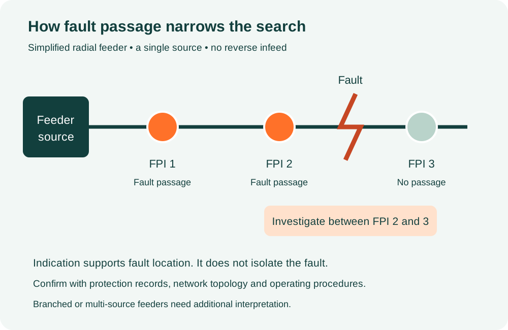
An FPI records a fault passage at its installed position; it does not interrupt fault current. Operators compare indications at successive locations with the feeder arrangement, protective-device events and switching records to narrow the search area. The actual faulted section must be confirmed by the utility operating team, especially on branched feeders or networks with more than one source.
Current sensing and fault recognition
The catalogue describes CT-based current sensing and an electronic assessment of current and voltage presence. Listed functions include phase-to-phase and phase-to-earth fault recognition, inrush discrimination, adaptive settings and identification of transient and permanent events. Detection behaviour depends on the ordered firmware, network earthing, fault-current level and protection-clearing time; these should be demonstrated during acceptance testing.
Visible indication and reset
A rotating red flag provides mechanical indication, while red, green and yellow LEDs communicate fault and device states. The brochure describes six fault LEDs plus one yellow status LED. Reset options include restored line current, restored voltage under no-load conditions and an adjustable timer. A site-specific indication legend and reset schedule should form part of the commissioning record.
Power and communication
The product illustration shows solar charging and CT-derived charging above 5 A, a 3.2 V 600 mAh rechargeable battery and a 3.6 V 2700 mAh backup battery. The exact chemistry, charging arrangement, replacement procedure and battery autonomy must be confirmed for the supplied revision. A compatible MPE306.1 handheld tool supports local parameter access, while an MPE309 DCU can forward events and measurements to a remote system.
Where MPE can support the project
MPE can review the feeder layout, required installation points, conductor compatibility and communication scope before preparing a proposal. Equipment selection, mounting arrangements, settings, tests, documentation and any monitoring integration are agreed against the project specification. This catalogue describes overhead equipment; underground-cable or RMU fault indicators require a separate product selection.
Technical data and selection notes
Values below are transcribed or paraphrased from the supplied manufacturer catalogue. Entries marked for confirmation must be settled in the offered data sheet and approved project documents.
| Model / network | MPE308.1 / overhead lines |
|---|---|
| Voltage class | Catalogue summary: 6–70 kV; technical table: 2–110 kV. Confirm the ordered voltage class. |
| Current range | Technical table: 0–1,200 A; separate measurement claim: up to 2,000 A. Confirm measurement and withstand limits separately. |
| Frequency | 45–60 Hz |
| Conductor diameter | 10–40 mm bare conductor, as listed |
| Short-circuit withstand | 31.5 kA for 4 s, catalogue claim; require the relevant test evidence |
| Voltage-resistance entry | 125 kV listed; test waveform and duration are not identified |
| Enclosure protection | IP68, catalogue claim |
| Operating temperature | −40°C to +85°C |
| Radio interface | 433 MHz to compatible handheld / DCU |
| Automatic reset timer | 2 minutes to 48 hours, configurable |
| Flashing timing | 5 s interval and 50 ms duration listed as configurable |
| Indication visibility | Catalogue claims 100 m by day / 300 m at night; site visibility varies |
| Dimensions / mass | W75 × H185 mm / 0.75 kg, listed values |
| Static consumption | 12 μA, listed value |
| Service life | 10 years stated; not a project warranty or assured battery life |
Fault-section sketch
Build the right FPI scope for your network
Share your feeder diagram and monitoring requirements. MPE can review equipment selection, supply, installation coordination and commissioning support as an agreed project scope.
Equipment selection, supply, installation coordination, testing and commissioning support for overhead fault indication and monitoring systems. Share your feeder diagram, voltage level, conductor details and SCADA requirements for a project-specific proposal.
Call / WhatsApp: +880 1558-607039 · Email: mechpowerengbd@gmail.com
Office: House-08 (GF), Road-06, Shekhertek Main Road, Dhaka 1207.
Factory: Ahasanpur, Bordeshi, Amin Bazar-1348, Savar, Dhaka, Bangladesh.
Final equipment ratings, test reports, integration scope, availability, software licensing and warranty terms are confirmed in the approved proposal.